 Dungeons and Difference
Embedded Infrared Sensor Demonstration Box
My lab has recently benefited from automation afforded by relatively simple infrared break beam sensors, which played no small part in prompting my dive into embedded systems. I’ve also joined an initiative focused on automation and technology, and I’ve started giving monthly talks to my colleagues to raise awareness about existing and available technologies to make their jobs easier and to gain efficiencies.
Last month’s inaugural talk was on solenoids, relays, and contactors — things which are commonplace at my facility. This month, I wanted to go a little more out there and exhibit some useful and affordable sensors with a small footprint.
Objective
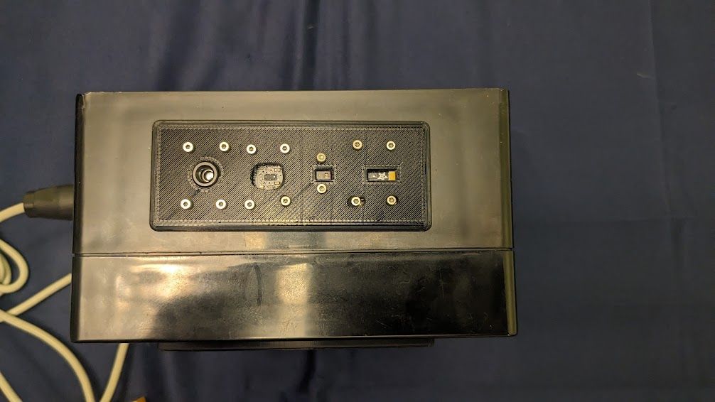
My goal was to create an interactive display that would not only exhibit the capabilities of different infrared sensors but also serve as a practical learning tool for my audience so that they might think of how they might automate some of their tasks in their respective areas. What I came up with was a box arrayed with multiple sensors with sensor data being displayed on a TFT display. The challenge was learning how to integrate multiple sensors into one coherent system and to provide a user-friendly interface with real-time visual feedback.
Materials
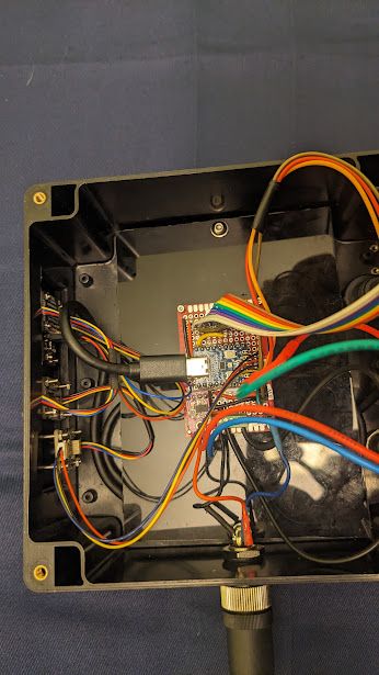
- Waveshare RP2040-Zero: I like these boards due to their small footprint and low price. I figured I would need the 264 KB of RAM on the RP2040, and I wound up making use of the dual core processor. Programmed in Arduino IDE.
- ABS Enclosure: 6.1” x 6.1” x 3.4” project enclosure to house the electronics.
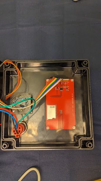
- Hosyond 3.5” SPI TFT LCD: This was listed as using a ILI9488 driver, but was rather a ILI9481. It has a resistive touch screen and SD card reader, but these features weren’t used.
- Rotary Switch: Implemented for sensor selection, providing tactile feedback and fixed positions corresponding to each mode.
- Passive Components: Comprising nine 1kΩ resistors and a 10uF capacitor to support the rotary switch functionality
- Adafruit MPM3610 Buck Converter Breakout: 6–21V to 5V buck converter providing 1.2A current.
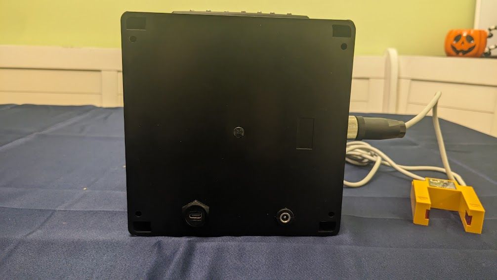
- Female 2.1 mm DC Power Jack: For DC barrel jack power to MPM3610.
- Panel Mount USB-C cable: For 5V power, programming, and USB serial.
- 3D Printed Bezels: Fabricated in PLA, these bezels ensured a neat and organized presentation of the sensors and display.
The suite of infrared sensors included the following breakout boards:
- JESSINIE PAJ7620U2 Gesture Recognition Sensor: For detecting hand gestures. I was originally going to use an Adafruit APDS-9960 breakout board, but there was an I2C address conflict with the AS7341. Rather than using the other I2C channel, this was an easy drop-in replacement.
- Adafruit VL53L4CX Time of Flight Distance Sensor: For accurate distance measurements using time-of-flight calculations up to 6000 mm.
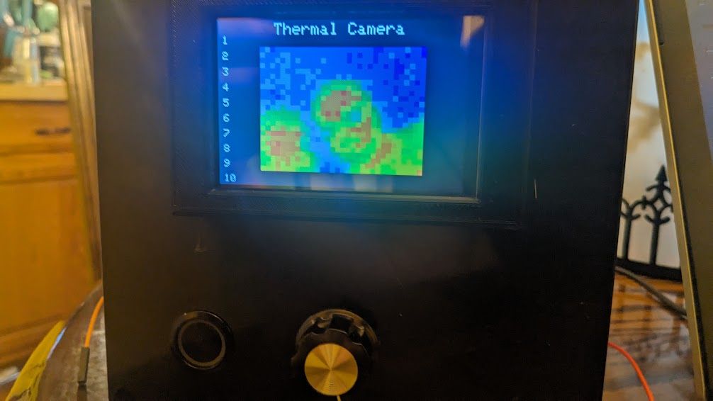
- Adafruit MLX90640 IR Thermal Camera: 32x24 pixel thermal imaging.
- Adafruit AS7341 11-Channel Spectral Sensor: For light measurement centered at 8 visible wavelengths and 1 NIR band.
- Uxcell E3S-GS30E4 Infrared Fork: For simple object detection. Unlike the above, which are all on the I2C bus, this was connected via an M12 connector to power, ground, and a digital pin.
Technical Details
This was perhaps my most ambitious project thus far. While any of these on their own would have made for a relatively simple task, I had to grapple with multiple sensors and their respective libraries. I wanted a simple and coherent output as to not distract from what was being demonstrated.
Keep in mind, I lack formal education in coding, and my methodologies aren’t perhaps the best, but they proved to be viable for the intended task of demonstration. I would not recommend any of my approaches for production or applied usage.
Power
The device can be powered directly from USB or via a 2.1mm center positive barrel jack.
Tft Display
I used the TFT_eSPI library for the TFT display and updated the user config. I created several functions for updating the display between modes and for displaying sensor data.
The display consisted of the following elements:
- Top: Title of the Sensor/Mode
- Left: Vertical Menu with an arrow drawn pointing next to the current mode
- Center: Sensor output; alphanumeric for all except the thermal camera
I know there were a lot of missed opportunities, but I hadn’t used an LCD in any of my projects prior to this. I learned a lot about the limitations of the SPI interface, but I was able to get relavent portions to update without flicker.
Rotary Switch
Resistors were soldered in series along the throws of a 10-position rotary switch to create a resistor ladder in order to create what is effectively a stepped potentiometer. A rotary encoder would have probably done just as well here, but I liked the idea of having fixed positions with a satisfying click. Here the ADC matches the voltage to a mode. I later soldered a 10 uF capacitor from the pole to ground as a hardware debounce.
Since I knew that between the sensors and display, this would be rather resource intensive, I didn’t want the ADC being polled constantly in the main loop, so I experimented by having the other M0+ core handle that and push any updates.
To invoke core1 using the Earle Philhower core for the RP2040, you simply need to add setup1 and loop1. To avoid a race condition, I made use of the FIFO system.
void loop1()  {
    static int lastPosition = 0;
    int position = getSwitchPosition();

    if (position != lastPosition) {
        // Position changed, push the new position to core0
        while (!rp2040.fifo.push_nb((uint32_t)position)) {
        }
        lastPosition = position;
    }
}
So if there is a change in position, a shared variable is pushed to the FIFO. If the FIFO is populated, core0 will make the necessary changes.
void loop() {
  uint32_t newPosition;
  // Check if there's new data from core1 about switch position
  if (rp2040.fifo.pop_nb(&newPosition)) {
      // Handle the new position
      updateSwitchDisplay(newPosition);
  }

  //  ... [Change modes]
    }
And there’s that, my first forray into multicore programming. At 133 MHz clock speed, it may not have been absolutely necessary, but it was nonetheless satisfying to successfully offload the ADC polling to the other core.
Switching Modes
When it came to handling each sensor, I wanted a modular solution to streamline the coding. I chose to create a class for each sensor that would inherit from a base sensor class. This base class contained virtual methods for initializing the sensor, prepping the display between modes, and displaying the data on the TFT. Each derived class then implemented these methods with sensor-specific code.
Here’s a simplified version of what the base class and a derived class look like:
// MLX90640 Thermal Camera
class ThermalSensor : public Sensor {
private:
    // Properties for MLX90640 here

public:
  void setup() override {
    // Initialize MLX90640
  }

    void prepare() override {
      // Clear TFT, change I2C clock speed, etc
    }

  void updateDisplay() override {
    // Map palette to sensor data, update TFT
  }
};setupis what a standalone sensor’s setup would entail; actually runs during the mainsetuploop.prepareupdates the header, clears any previous sensor output, and changes the I2C clock because the MLX90640 runs at 1 MHz while the others run at the default 400 kHz.updateDisplayworks as you would expect the main loop to look for a standalone sensor.
An array of pointers to Sensor objects is declared, with each pointer pointing to an instance of a derived sensor class. So as was elided in the main loop earlier, the instance is called thusly:
if (newPosition >= 1 && newPosition <= NUM_POSITIONS && sensors[newPosition - 1]) {
        sensors[newPosition - 1]->updateDisplay();
    }
Was this the best approach? I couldn’t tell you at this point; I didn’t run into any issues with memory. This is certainly an area I want to explore further.
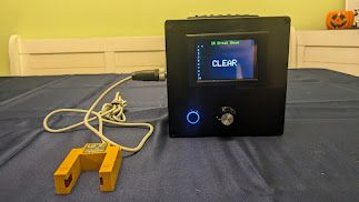
Infrared Fork
Infrared forks are self-contained packages consisting of an IR LED and an open collector phototransistor. In this case a digital high pin is pulled to ground like a switch or button press. I created three modes for this, as it was perhaps the simplest of all.
- Simple On/Off: This displays “BLOCKED” when the beam is interrupted and “CLEAR” when there is no obstruction. This is one of the ways my lab units make use of these sensors.
- Counting: Every time the beam is blocked, a counter goes up in increments of 1. My automated units make use of small photointerrupters as slot encoders.
- Timer: This displays the time between blocking. One could easily have multiple forks and divide the time by their distance to calculate the speed of an object passing through.
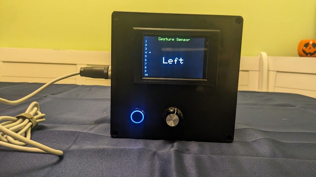
Paj7620u2 Gesture Sensor
Though lacking the convenient Stemma Qt connector found on Adafruit breakout boards, this was an easy replacement for the APDS-9960. Firstly, I wasn’t looking to demonstrate the RGB or proximity modes, but I believe the PAJ7620U2 is actually more responsive. I used the DFRobot_PAJ7620U2 library.
Here the detected gesture would be displayed on the screen and go blank after 2 seconds if there were no other gestures detected. There are 4 axes:
- up-down
- left-right
- forward-backward
- clockwise-counterclockwise
More complex gestures are possible, but for demonstration purposes those above were sufficient.
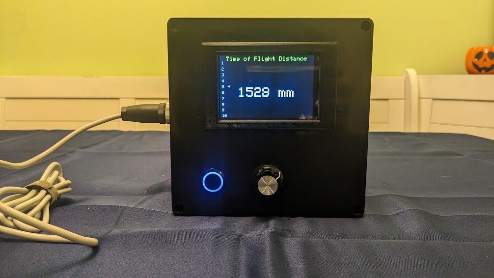
Vl53l4cx Time of Flight Distance Sensor
ToF distance sensors can be used for rangefinding, object detection, and volume calculations.
Here I used STM32’s vl53l4cx_class library. I can’t say I was very thrilled with their provided examples, as they seemed to include unnecessary libraries and pointers. This was also challenging because the sensor updated faster than the display could keep up, so I included a non-blocking delay. This sensor and library have the potential to be very powerful, but distance alone was sufficient for my demonstration.
As7341 Spectral Sensor
Working in laboratories, we of course have spectrometers, but I thought that perhaps a simple one could have an application in detecting change in turbidity, quality concentration, etc.
I used Adafruit’s Adafruit_AS7341 library. Due to a lack of screen real estate, I limited myself to three wavelengths. I originally wanted to display these graphically, but opted not to due to time constraints.

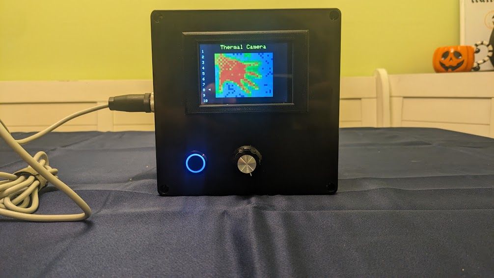
Mlx90640 Thermal Camera
For general safety, hot spot detection, and hunting down your enemies, you can’t go wrong with a thermal camera.
Here, I used Adafruit’s Adafruit_MLX90640 library and adapted their example to TFT_eSPI. I wanted to add a scale and an average temperature, but lacked the time to do so.
Challenges
Screen Size
So 3.5” is nice and roomy as far as hobbyist displays go, but when you’re presenting to a room of 25 people, it’s probably not the best. My hair-brained solution was to use PuTTY to read off the serial port and have VBA read off the last line of the log to update a text box in a PowerPoint presentation. I actually got this to work at my desk, but for some reason my macro wouldn’t run when it came to showtime, and I wasn’t going to troubleshoot while I was in the spotlight, so I just showed everyone the PuTTY terminal when I was showing examples. It was not as smooth as I would have liked, but at least the folks in the back could see something.
Mounting Sensors
The MLX90640 was, by far, the easiest to mount since there is a recess that snap fits into the bezel. The PAJ7620U2 was next because the sensor IC is mounted on one side of the board and the supporting passive components are on the reverse. Unfortunately, as much as I love Adafruit’s Stemma Qt breakout boards, the Stemma Qt connectors and passive components get in the way of a flush mount with the bezel designed with my meager CAD skills. I wasn’t ready to desolder the connectors either, as I might want to repurpose the breakouts for another project.
I also erred by saving mounting for the last minute (i.e. the morning of the presentation) and discovered there were misalignments. I did my best with the dremmel to get everything in and stable enough for transport and demonstration.
Results
I couldn’t tell from the absolute silence of the room that Monday morning, but throughout the week reviews started to filter in, and those I talked to at least found it interesting. By Friday someone stopped me in the hall and asked “who can I talk to to implement this stuff in my area?” Be still my heart! As far as I’m concerned, that was a success.
Now I need to actually start developing solutions for myself and start conversations with our engineering group to start designing and deploying these things in my immediate area.
Project code can be found here.
Future Improvements
Screen Scalability
From an educational perspective, the limited size of the TFT display presents a challenge in group settings. Future iterations could include an DVI output to allow for larger displays or projectors, making demonstrations more effective for larger audiences.
Software Robustness
The software, while functional, could be further refined. More sophisticated error handling and data processing could be implemented to ensure stability and performance during extended use or under unexpected operating conditions. That, of course, will come with my own maturity in coding such systems.
Sensor Accessibility
The Stemma Qt connectors, while convenient for prototyping, posed a problem for flush mounting. A custom PCB could be developed to mount all sensors more securely and neatly, with the added benefit of reducing wiring complexity. Alternatively, a different bezel could be designed and fabricated to accommodate the geometries of the breakout boards.
Expandability
Designing the system with expansion in mind — perhaps by including I2C multiplexing or additional input ports — would make it easier to integrate new sensors or components without having to redesign the entire system. Portable modules with EEPROM and edge connectors could be used to hot swap sensors.